


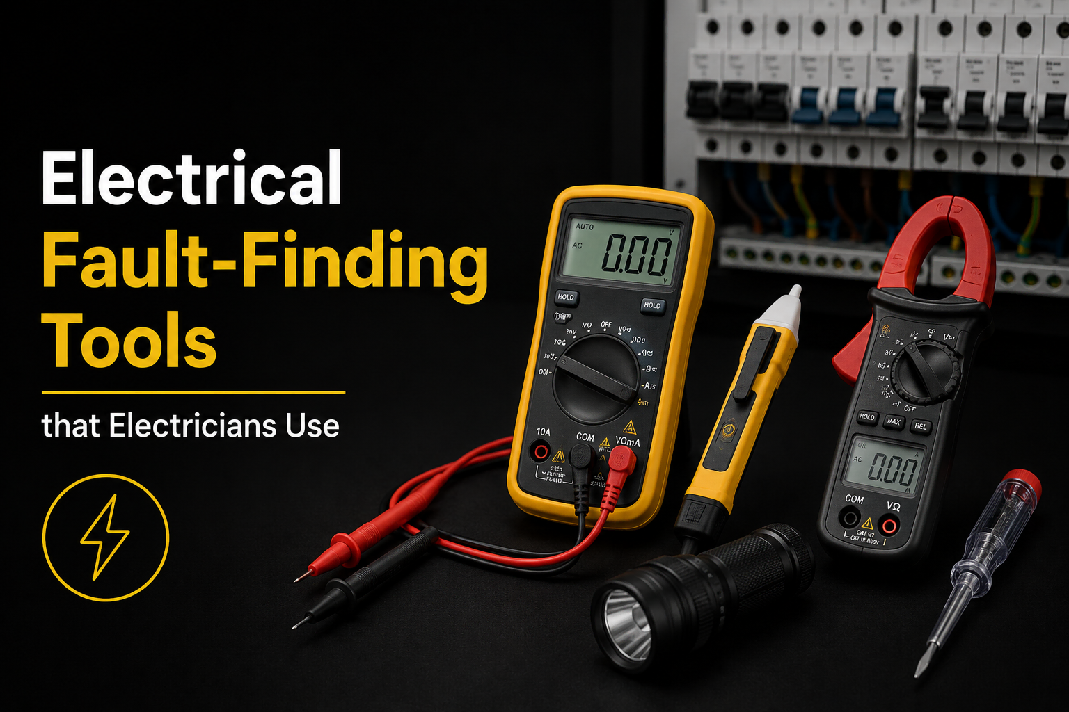

Electricians use a small set of specific instruments to find electrical faults a voltage indicator, a multimeter, a clamp meter, an insulation resistance tester, and a multifunction tester that combines several of these functions in one device. Each one answers a different diagnostic question, and none of them “find the fault” on its own.
This isn’t a buying guide, and we’re not selling test equipment. What follows is an explanation of what each tool actually reveals during a professional diagnosis, what it doesn’t tell you, and why owning one of these instruments isn’t the same as knowing what the reading means.
Why the Tool Matters Less Than the Question It’s Answering
A test instrument gives you a number. It doesn’t give you a diagnosis.
An insulation resistance reading of 0.8 megohms means something completely different on a lighting circuit than it does on an outdoor socket circuit that’s just had heavy rain. A clamp meter showing 12 milliamps of leakage means something different depending on how many other circuits share the same RCD. The instrument measures. The electrician has to interpret that measurement against the fault history, the circuit’s condition, and the results of other tests which is the whole reason our guide to how electricians find electrical faults treats fault finding as a process, not a single test.
Voltage Indicator and Safe Isolation
Before any other test happens, the circuit needs to be confirmed dead. A voltage indicator sometimes a two-pole tester, sometimes a non-contact detector used as an initial check confirms whether a circuit is live or safely isolated.
This step comes first because every other test on this list either requires the circuit to be isolated, or requires knowing for certain that it isn’t. Skipping it, or relying on a non-contact detector alone without proving dead at the point of work, is one of the more common ways DIY electrical testing goes wrong.
Multimeter: What It Measures, and What It Doesn’t
A multimeter measures voltage, resistance and continuity at a single point. It can confirm whether a socket is receiving the expected voltage, whether a fuse or cable has continuity, or whether a connection is providing the resistance it should. What it can’t do is measure current safely on a live circuit without breaking into it, which is where a clamp meter takes over. A multimeter also can’t tell you why a reading is what it is a low resistance reading tells you there’s a short path somewhere, not where that path is or what caused it.
Clamp Meter: Measuring Leakage Without Breaking the Circuit
A clamp meter measures current flowing through a conductor by reading the magnetic field around it, without needing to disconnect anything. Placed around the live and neutral conductors together, it can reveal any imbalance between the two which is exactly what earth leakage is. This makes it one of the more useful instruments for investigating a tripping RCD, because it lets an electrician measure actual leakage on a live circuit rather than guessing at it. Our guide to what earth leakage actually is explains why even a normal, healthy installation shows some reading here, and why the number on its own isn’t automatically a fault.
Insulation Resistance Tester: Checking the Condition of the Cable Itself
With the circuit safely isolated, an insulation resistance tester applies a test voltage typically 500V DC on standard circuits between conductors and earth, and measures how much current leaks through in response. Healthy insulation should show a very high resistance. A low reading points to insulation that’s degraded, damaged, or affected by moisture.
This is the test that confirms whether a suspected cable fault is real, rather than just suspected from the symptoms. It’s particularly relevant where a fault is thought to be concealed our pillar guide covers how hidden and intermittent faults are narrowed down before anyone needs to open a wall.
Continuity and Polarity Testing
Continuity testing confirms that a conductor which should carry current all the way along its length actually does useful for finding a break in a cable, a protective conductor, or a ring final circuit that’s lost its loop.
Polarity testing confirms that live, neutral and earth are connected the right way round throughout a circuit. Reversed polarity doesn’t always cause an obvious symptom, which is part of why it needs testing for rather than assuming.
Earth Fault Loop Impedance
This test measures the total resistance of the path a fault current would take if a live conductor touched an earthed part from the source of supply, through the fault, and back to earth. A low enough impedance confirms the protective device will disconnect fast enough if that fault ever occurs. It’s a test about the circuit’s protective arrangement as a whole, rather than a specific fault. It becomes particularly relevant when investigating whether a protective device is actually capable of doing its job which connects directly to understanding why an MCB catches a short circuit and an RCD catches an earth fault in the first place.
RCD Tester
An RCD tester applies a controlled leakage current and times how long the RCD takes to disconnect. This confirms whether the device is actually operating within the required time, rather than just assuming it works because it trips occasionally. This matters because an RCD that trips doesn’t necessarily mean it’s working correctly it could be tripping too slowly, or at the wrong current level, and a tester is the only way to actually confirm its performance rather than its presence.
Thermal Imaging: What Heat Reveals, and Its Real Limits
A thermal imaging camera shows surface temperature differences across a consumer unit, a connection, or a run of cable. A connection running hotter than its surroundings under load often points to a poor connection or an overloaded circuit before it fails completely. The limit is just as important as the capability. Thermal imaging shows heat on the surface it can’t see inside cable insulation, and it can’t detect a fault that isn’t currently generating heat. A cable with damaged insulation that isn’t under enough load to warm up won’t show anything unusual on a thermal image, which is why it’s used alongside other tests rather than instead of them.
Cable Tracer: Locating a Run, Not Confirming a Fault
A cable tracer sends a signal along a conductor and uses a receiver to follow that signal’s path, which helps establish where a concealed cable actually runs behind a wall, under a floor, or through a loft space.
This is worth being clear about: a cable tracer finds the cable, not the fault. Knowing where a cable runs is genuinely useful once testing has already narrowed a problem down to that specific cable it turns “there’s a fault somewhere in this wall” into “the cable runs along this specific line,” which limits how much needs to be opened up. It doesn’t, by itself, tell you whether that cable has actually failed.
What a Single Reading Can’t Tell You on Its Own
Any one of these readings, taken in isolation, is a data point not a diagnosis. A clamp meter reading of 15mA doesn’t confirm a fault without knowing how many circuits share that RCD. An insulation resistance reading close to the minimum acceptable value doesn’t confirm failure without knowing the cable’s age, its route, and whether the same pattern shows up elsewhere in the property. A hot spot on a thermal image doesn’t confirm the cause without a follow-up test to establish what’s actually generating that heat.
This is the actual difference between fault finding and simply pointing an instrument at something. The value isn’t in owning the equipment it’s in knowing which test answers which question, and reading the results together rather than in isolation.
Why This Isn’t a Buying Guide
We’re an electrical contracting business, not a tool retailer, and we don’t sell test equipment. If you’re comparing meters or testers to buy for yourself, that’s a different question from the one this page is answering.
What’s covered here is what happens during a professional diagnostic visit, and why the equipment on its own isn’t what makes the diagnosis correct. Interpreting a reading safely and accurately depends on training, experience, and testing carried out in the right sequence not on which brand of meter is in the toolbox.
Frequently Asked Questions
What tools do electricians use to find electrical faults?
The core set includes a voltage indicator for safe isolation, a multimeter, a clamp meter, an insulation resistance tester, and often a multifunction tester that combines continuity, insulation resistance, loop impedance and RCD testing in one instrument.
Can I find an electrical fault myself with a multimeter?
A multimeter can confirm basic things like whether a socket has voltage or a fuse has continuity, but interpreting what a reading means and testing safely on live circuits or with the correct isolation requires training. Fault finding is a process, not a single measurement.
What’s the difference between a multimeter and a clamp meter?
A multimeter measures voltage, resistance and continuity at a point, usually requiring a connection to the circuit. A clamp meter measures current flowing through a conductor without breaking into it, which makes it useful for checking leakage on a live circuit.
Does thermal imaging find every electrical fault?
No. It reveals heat on the surface of a connection or cable, which is useful for spotting overloaded or failing connections under load. It can’t detect a fault that isn’t currently producing heat, or see damage inside cable insulation.
Can a cable tracer find a fault behind a wall?
A cable tracer locates where a cable physically runs, which helps narrow down where a concealed fault might be. It doesn’t confirm whether the cable is actually faulty that still requires testing once the relevant section is identified.
Why do electricians use so many different tools instead of one device?
Each instrument answers a different question whether a circuit is safe to isolate, whether current is leaking, whether insulation has degraded, whether a protective device is working correctly. No single tool answers all of these, which is why a proper diagnosis usually involves several tests rather than one reading.
Need a Professional Diagnosis in Hounslow or West London?
If you have an electrical fault and want it properly diagnosed rather than guessed at, Handy Electric Pro provides electrical fault finding across Hounslow, Twickenham, Feltham, Isleworth, Richmond, Brentford and the wider West and South West London area.
Muhammad Arif is an ECS Gold Card qualified electrician and NAPIT-approved contractor, and every diagnostic visit follows the same tested, systematic process regardless of which instruments the specific fault requires.
Book Online